Fibre Channel Layers
Fibre Channel Protocol is split into five layers. It does not follow the OSI model, although it is quite similar.
- FC-0 – Describes the physical media + the speed in which that device can communicate (1,2, 4, 8, 10, 16 Gbps)
- FC-1 – Contains specifications for encoding, ordered set, and link control communications.
- FC-2 – Create FC Frame and flow control. We need flow control to check how much data we can send at a given time, so the receive side can handle all the request. Flow control is handle by buffer-to-buffer control credit.
- FC-3 – Largely unused. Common Fabric Services; Defines advanced features, such as stripping and hung group
- FC-4 – Provides mapping of Fibre Channel capabilities to Upper Layer Protocols. The most popular will be SCSI. FCP – Fibre Channel Protocol is used to denote the SCSI over Fibre Channel.
FC-0
When it comes to cabling, Fiber is available as a single mode or multi-mode cable. The main diference is the smaller the glass core, the grater the distance data can travel. In other words single mode cable, which is 9 micron thick (human hair ~75 micron thick) can be much longer (up to 10 km) than multi-mode cable, which is 50 (or 62,5) micron – which should not be longer than 150meters. Typically multi-mode cables are either light blue, or orange, where-as single-mode cables are yellow.
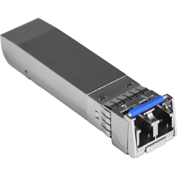
SFP – small form-factor pluggable is a compact transceiver used for data communication. This device is designed for use with Fibre cable connectors. It’s hot-swappable installed on switches/hosts/storage ports. XFP are cable of transmitting at 10 Gbps speeds.
FC-1
Encoding is a process where parallel electrical singal is encoded into serial optical signal. Speed 1,2,4 and 8 Gbps uses 8bit/10bit encoding. Speed 10 and 16 Gbps are using encoding 64bit/66bit (less overhead). For every 8 bits (or 64bits) that are transmitted there are extra 2 bits that are sent in order to detect link control communication issues etc.
FC-2
This layer defines frame structure, class of service and flow control.
Classes of Service – There are 1,2,3,4,6,F Classes of devices. Classes of service defines the flow control (either Buffer-to-Buffer – between switch port and the device – for example in Class 3, or End-to-End – between device and device, bypassing the switch buffer credit model – eg. Class 2). Class F is for E_Ports – switch-to-switch communication.
Fibre Channel Frame has a header and may have a payload. Header contains control and addressing information. Where-as payload contains the information being transported form Upper Level Protocol (FC-4).
Header has elements such as Destination_ID, Source_ID. Payload is max of 2112 Bytes, but the frame doesn’t have to fill-up the payload with zero’s if it is empty. The minimum Fibre Channel frame is 64 Bytes.
Flow Control mechanisms
- ACK – Acknowledgement – for Class 2 communication (uses EE_Credit – End-to-End)
- R_RDY – Receiver_Ready – for Class 3 communication (uses BB_Credit)
- VC_RDY – Virtual Circuit Ready – for class 6 communication (uses BB_Credit)
Fibre Channel do not allow dropping of frames in steady state. As a consequence a device must never send frames without the receiving device being albe to receive them. When all BB credits are utilized, a device will wait for an R_RDY from the destination beforre resuming operations.

