SAN / Brocade

Brocade – Introduction to NPIV (N_Port ID Virtualization)

In my last few posts I have written about Fibre Channel Layers, Port Initialization Process and Shared Area Addressing. In this post I would like to discuss NPIV (which was already mentioned here).

What is NPIV and why do we need it?

NPIV stands for N_Port ID Virtualization. As you already know, physical server has it’s own HBA card with it’s own private WWN. This WWN can be logged into the Fabric, and (for example) storage array can mask some LUNs only to this WWN. This gives the possibility to provide independent storage access. But what about Virtual Machines? Those doesn’t have their own, dedicated, physical HBA ports. Here NPIV becomes handy. Without NPIV all storage ports and LUNs are exposed to all virtual machines (in given environment).

As mentioned already, virtual machines shares the same physical HBA card (in single “vm environment” – for example ESX cluster). With NPIV, a HBA can present up to 255 unique World Wide (Port) Names (pWWNs) to a switch. If Fabric Switch supports NPIV, then it can assign uniq fabric port IDs to each virtual server (if you want to more know –  Shared Area Addressing post).

How does it work from the storage point of view?

Now this is getting interesting. Since single HBA can have up to 255 unique pWWNs you (or VM admin) can assign a unique pWWN to each Virtual Machine (of course with above 255 limitation). With that possible, you can create a seperate zone between this VM pWWN(s) and Storage. As a consequence, standard fabric zoning and storage LUN masking can be used. No additional configuration is needed from Storage point of view. A standard zoning/masking mechanisms can be used to isolate storage ports and LUNs to the appropriate virtual server – the same way, as you already do with your physical servers.

Brocade – Shared Area Addressing

With this short entry I would like to continue a little bit with concept explained in Fibre Channel Addressing post. Remember the 24bit FC Address? Let me put the same small image one more time:

24-bit Port Addressing scheme

24-bit Port Addressing scheme

As you can notice, the Area ID has 8 Bits. Within 8 Bits we can write down two (hex) numbers, which gives us possibilities to represents values 0 – 255 ( hex: 0x00 – 0xff). But what if our Switch (for example Brocade Director) has more than 255 ports? Now, here Shared Area Addressing is becoming handy.

In a few words, a shared area is an Area ID that exist more than once in a single domain. Keep in mind, each port has to have a unique FC Address, those shared areas are differentiated by their Node Address. In oder words, the Area ID is “borrowing” 1 bit from the Node ID and changing it to 1 ( binary 10000000 = hex 80). This 1 bit is used to address ports 256-383.  If that is changed, it is calculated as Area ID  + Node Address  8  (all in hex) Let me give you few examples:

  • Port Address 01a800 – Area ID = 0xa8 (hex) = Port Index 168
  • Port Address 01a900 – Area ID = 0xa9 (hex) =  Port Index 169
  • Port Address 01ff00 – Area ID = 0xff (hex) = Port Index 255  (last possible Port Index without Shared Area)
  • Port Address 018880 = 0x88 + 0x80 – 0x8 (hex) = 136 + 128 – 8 (dec) = Port Index 256
  • Port Address 018980 = 0x89 + 0x80 – 0x8 (hex) = 137 + 128 – 8 (dec) = Port Index 257
  • Port Address 01a880 = 0xa8 + 0x80 – 0x8 (hex) = 168 + 128 – 8 (dec) = Port Index 288

Now this “equation” is not always right, in some cases it is calculated based on equation Area ID + Node Address + 8 (all in hex)

To be completely honest with you, I cannot understand when we should add 8, and when we should subtract 8. If you understand this, I will really appreciate an explanation for example in “comments” section 🙂


Brocade – to which port my WWN is connected?

In this entry I would like to go through some practical question you may come access with. You know the WWN, and you wish to find it physically on SAN/switch level. First information you need is the exact location (switch, which Slot/Port). If you have just one switch Fabric, you can go with switchshow command and just go through the output. But what if your fabric has many switches? You can go with the command nodefind <alias_name> or nodefind <wwn> (or nodefind 0x<PID>). Example:

switch01> nodefind 50:06:04:8a:d5:4f:23:10
Remote:
    Type Pid    COS     PortName                NodeName
    N    40a500;      3;50:06:04:8a:d5:4f:23:10;50:06:04:8a:d5:4f:23:10;
        FC4s: FCP
        PortSymb: [38] "EMC SYMMETRIX 000000000001   "
        NodeSymb: [38] "EMC SYMMETRIX 000000000001   "
        Fabric Port Name: 20:02:00:05:1e:32:12:01
        Permanent Port Name: 50:06:04:8a:d5:4f:23:10
        Device type: Physical Initiator+Target
        Port Index: 165
        Share Area: No
        Device Shared in Other AD: No
        Redirect: No
        Partial: No
    Aliases: Symm0001_alias1

Let’s analyze the output.

  • Remote means that this WWN is connected to another switch in the Fabric.
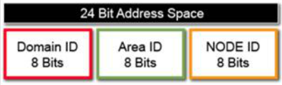
  • 40a500 – is a 24bit (Core PID format) FC Address. I mentioned FC Addressing in Fibre Channel addressing entry if you wish to refresh the knowledge. But in few words – First 8 bits are Domain ID, another 8 bits are Area ID, and last 8 bits are Node ID – 00 or AP_PA, so:
    • 40 – this is the Domain ID
    • a5 – this is the Area ID – a5 hex = 165 dec. As you can see this is exactly – our Port Index.
    • 00 – this is the Node ID –  00, because to this port only one Node is connected directly / No NPIV. If this switch required shared area addressing (basically more than 255), the first 8 bit of Node ID would be “borrowed” as Area ID as well.
  • Port Index: 165 – is already given (as hex) in Core PID Address.

So – we have a lot. We know the FC Address of our port, we know to which Domain it belongs and exactly to which port. Now we have a final step – to identify which switch is it. For that just go with the command fabricshow:

switch01> fabricshow

Switch ID   Worldwide Name           Enet IP Addr    FC IP Addr      Name
-------------------------------------------------------------------------
 23: fffc17 10:00:00:05:1e:13:1c:22 192.168.100.3  0.0.0.0        >"switch01"
 24: fffc18 10:00:00:05:1e:13:6e:f2 192.168.100.3  0.0.0.0        "switch04"
 62: fffc3e 10:00:00:05:1e:13:0a:13 192.168.75.1  0.0.0.0         "switch02"
 64: fffc40 10:00:00:05:1e:55:63:3d 192.168.100.3  0.0.0.0        "switch05"
101: fffc65 10:00:00:05:1e:55:33:11 192.168.75.2  0.0.0.0         "switch06"
105: fffc69 10:00:00:05:1e:32:64:01 192.168.117.1 0.0.0.0         "switch07"

Above we see the output of our Fabric. What interests us is the ID of the Switch. FFFCxx is the Address of the Domain Controller – xx represents the Domain ID. This is considered as the name/ID of the switch. And there it is – our Switch with Domain_ID=40 is switch05.

Now we can actually execute the same nodefind command on switch05:

switch05> nodefind 50:06:04:8a:d5:4f:23:10
Local:
    Type Pid    COS     PortName                NodeName
    N    40a500;      3;50:06:04:8a:d5:4f:23:10;50:06:04:8a:d5:4f:23:10;
        FC4s: FCP
        PortSymb: [38] "EMC SYMMETRIX 000000000001   "
        NodeSymb: [38] "EMC SYMMETRIX 000000000001   "
        Fabric Port Name: 20:02:00:05:1e:32:12:01
        Permanent Port Name: 50:06:04:8a:d5:4f:23:10
        Device type: Physical Initiator+Target
        Port Index: 165
        Share Area: No
        Device Shared in Other AD: No
        Redirect: No
        Partial: No
    Aliases: Symm0001_alias1

Of course as a consequence in Fabric every switch has always unique Domain_ID, therefore unique Domain Controller Address, therefore unique ID. It is called Embedded Port and it is necessary to route information between switches within one Fabric.