SAN / Brocade

Fibre Channel Layers

Fibre Channel Layers

Fibre Channel Protocol is split into five layers. It does not follow the OSI model, although it is quite similar.

  • FC-0 – Describes the physical media + the speed in which that device can communicate (1,2, 4, 8, 10, 16 Gbps)
  • FC-1 – Contains specifications for encoding, ordered set, and link control communications.
  • FC-2 – Create FC Frame and flow control. We need flow control to check how much data we can send at a given time, so the receive side can handle all the request. Flow control is handle by buffer-to-buffer control credit.
  • FC-3 – Largely unused. Common Fabric Services; Defines advanced features, such as stripping and hung group
  • FC-4 – Provides mapping of Fibre Channel capabilities to Upper Layer Protocols. The most popular will be SCSI. FCP – Fibre Channel Protocol is used to denote the SCSI over Fibre Channel.

FC-0

When it comes to cabling, Fiber is available as a single mode or multi-mode cable. The main diference is the smaller the glass core, the grater the distance data can travel. In other words single mode cable, which is 9 micron thick (human hair ~75 micron thick) can be much longer (up to 10 km) than multi-mode cable, which is 50 (or 62,5) micron – which should not be longer than 150meters. Typically multi-mode cables are either light blue, or orange, where-as single-mode cables are yellow.
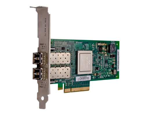
SFPsmall form-factor pluggable is a compact transceiver used for data communication. This device is designed for use with Fibre cable connectors. It’s hot-swappable installed on switches/hosts/storage ports. XFP are cable of transmitting at 10 Gbps speeds.
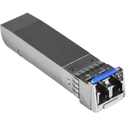
SFP

SFP


FC-1

Encoding is a process where parallel electrical singal is encoded into serial optical signal. Speed 1,2,4 and 8 Gbps uses 8bit/10bit encoding. Speed 10 and 16 Gbps are using encoding 64bit/66bit (less overhead). For every 8 bits (or 64bits) that are transmitted there are extra 2 bits that are sent in order to detect link control communication issues etc.

FC-2

This layer defines frame structure, class of service and flow control.

Classes of Service – There are 1,2,3,4,6,F Classes of devices. Classes of service defines the flow control (either Buffer-to-Buffer – between switch port and the device – for example in Class 3,  or End-to-End – between device and device, bypassing the switch buffer credit model – eg. Class 2). Class F is for E_Ports – switch-to-switch communication.

Fibre Channel Frame has a header and may have a payload. Header contains control and addressing information. Where-as payload contains the information being transported form Upper Level Protocol (FC-4).

Fibre Channel Frame

Fibre Channel Frame

Header has elements such as Destination_ID, Source_ID. Payload is max of 2112 Bytes, but the frame doesn’t have to fill-up the payload with zero’s if it is empty. The minimum Fibre Channel frame is 64 Bytes.

Flow Control mechanisms

  • ACK – Acknowledgement – for Class 2 communication (uses EE_Credit – End-to-End)
  • R_RDY – Receiver_Ready – for Class 3 communication (uses BB_Credit)
  • VC_RDY – Virtual Circuit Ready – for class 6 communication (uses BB_Credit)

Fibre Channel do not allow dropping of frames in steady state. As a consequence a device must never send frames without the receiving device being albe to receive them. When all BB credits are utilized, a device will wait for an R_RDY from the destination beforre resuming operations.

Fibre Channel addressing

What is Fabric?

Fabric can be explained as a number of switching elements connected together. As I mentioned in part 1 Fabric can be just one switch, or bunch of interconnected switches (domains). One Fibre Channel Switch = one Fabric Domain.

Fabric

Fabric

Addressing

All devices in Fibre Channel network have an identity.

Worldwide name (WWN)

All FC devices have a unique identity that is called a worldwide name (WWN). This identification can be compared with Ethernet cards and MAC addresses. Each Node Port has its own WWN, but it is also possible for a device with more than one Fibre Channel adapted to have its own WWN as well. WWN is 64-bit address, and if two WWN addresses are put into the frame header, this leave 16 bytes of data just for identyfying the destination and source address. So 64-bit addresses can affect routing performance. Each device in the SAN is identified by a unique WWN. The WWN contains vendor identifier field, which is defined and maintened by the IEEE.

There are two WWN addressing scheme, old one starts with 10:00 followed by company ID and vendor specific info. New scheme start with hex 5 or 6 in the first half-byte followed by the vendor intenfier in the next 3 bytes:

WWN addressing scheme

WWN addressing scheme

Vendor ID and company ID are assigned by the IEEE standards, and can be found here:

http://standards.ieee.org/develop/regauth/oui/oui.txt

WWNN vs WWPN

A worldwide node name (WWNN) is a globally unique 64-bit identifier that is assigned to each Fibre Channel node or device. For servers and hosts, WWNN is unique for each HBA (host bus adapter), and in a case of a server with two HBAs, they have two WWNNs. For a SAN switch, the WWNN is a common for the chassis. For storage, the WWNN is common for each controller unit of midrage storage. In case of high-end enterprise storage, the WWNN is unique for the entire array.

A worldwide port number (WWPN) is unique identifier for each FC port of any Fibre Channel device. For server, we have a WWPN for each port of the HBA. For a SAN switch, the WWPN is available for each port in the chassis. For Storage, each host port has an individual WWPN.

Port address

Additionally to WWNs there is another addressing scheme that is used in Fibre Channel networks. This scheme is used to address ports in the switched fabric. Each port in the switched fabric has its own unique 24-bit address.

24-bit Port Addressing scheme

24-bit Port Addressing scheme

Those 24-bit addressess are used strictly for routing processes. It contains Domain ID, Area ID and Node ID.

  • Domain

This byte is the address of the switch itself. A domain ID is a unique number that identifies the switch or director to a fabric. One byte allows up to 256 possible addresses. Because some of these addresses are reserved, as for the one for broadcast, there are only 239 addresses available. This number means that you can theoretically have as many as 239 switches in your SAN environment.

  • Area

The area field provides 256 addresses. This part of the address is used to identify the individual ports. Hence, to have more than 256 ports in one switch in a director class of switches, you must follow the shared area addressing.

  • Port / Node

The final part of the address provides 256 addresses for identifying attached N_Ports and NL_Ports.

Introduction to Fibre Channel

What is Fibre Channel

In few words Fibre Channel combines the best of two worlds. It’s a channel transport that shares best of the characteristics of an I/OI bus (like SCSI), as a consequence hosts and applications see the disk devices as locally attached storage. But Fibre Channel also incorporates the best of the network as FC allows multiple protocol support, such as SCSI, IP, FICON.

At the beginning, when storage was connected directly to servers, it was a good solution due to high-speed channel from server to storage (most often SCSI Bus). The biggest limitaion was 15 devices for BUS. The limitation also was with sharing the data, clustering etc.

Parallel SCSI Bus

Parallel SCSI Bus

Due these limitations there was a need for network flexibility, keeping up the channel performance, as a block level data. These are the origins of the Storage Area Network (SAN). The dominant technology used in modern SANs is Fiber Channel. Biggest benefits of FC are:

  • Speed up to 16 Gbit/sec
  • Initiator negotiates for access before transmitting to the target, which gives channel-like access to the target
  • all SCSI commands and user data is sent over 212 bye Fibre Channel payload frames

Fabric => SAN

SAN and Fabric

SAN and Fabric

Fabric is a collection of Fibre Channel switches, Directors, and connected devices, such as server hosts and storage. Fabric is an most popular implementation of SAN.

SAN Components

SAN provides any-to-any connectivity in the fabric. SANs employ fiber optic and copper connections to create dedicated networks for servers and their storage systems. To do so, there are couple of components needed:

  • Fibre Channel Switches and/or Directors – note, the smalles Fabric is just one switch
  • HBAs (Host bus Adapters) – HBAs are similar to NICs (Network Interface Card). There are used to connect devices to Fabre Channel Switches. They replaced SCSI controllers.


Host Bus Adapter

Host Bus Adapter

  • Storage System
  • Optical cables
  • Management Software
  • Tape Drives – for backup purposes

In couple of next entries I will go a little deeper into SAN, I will explain more in detail what Fabric is, how the Fabric can be scalled-out, what are the different ports in the Fabric, etc.